Ammeter Gauge Wiring Diagram
Remove nut and washer from starter solenoid battery connection post a. Wire, connect the (i) terminal to a switched +12v source.
Amp Meter Wiring With Current Transformer In Urdu/Hindi Electrical Tutorials Urdu Hindi
The first component is symbol that indicate electrical component from the circuit.

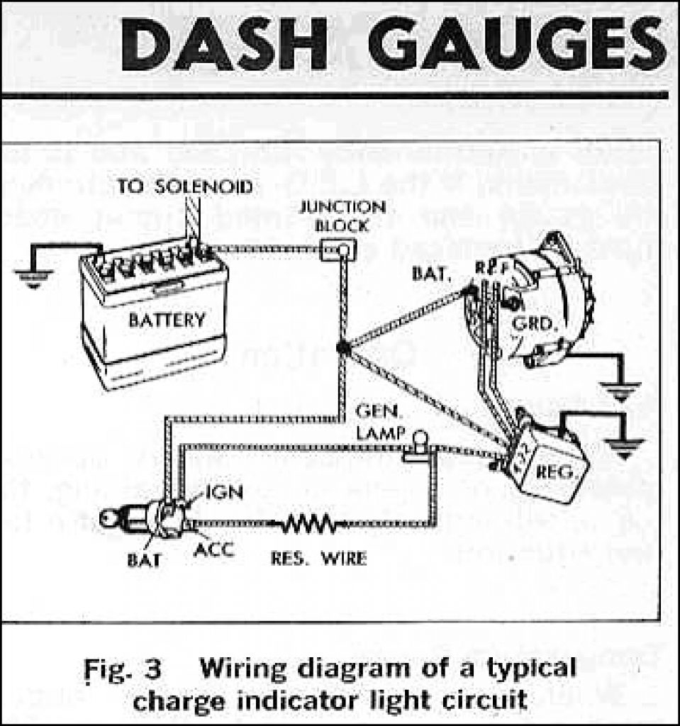
Ammeter gauge wiring diagram. Temperature gauge wiring (figure 3): Up to 20% cash back type connectors (diagram 4), to each end of both wires. Vehicle may contain fusible links.
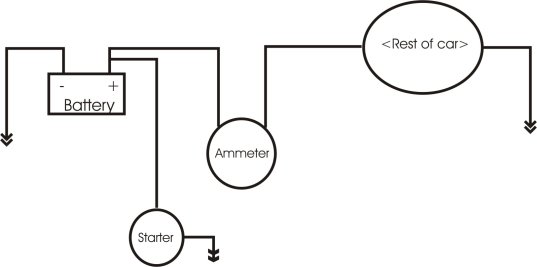
The hookup of the ammeter is a wire to the horn relay buss bar and the other gauge lead to the junction block next to the battery. An ammeter measures the amperage (volume of. 2) wire, minimum, with an insulation temperature rating of 220° f (105° c), minimum, from the battery terminal
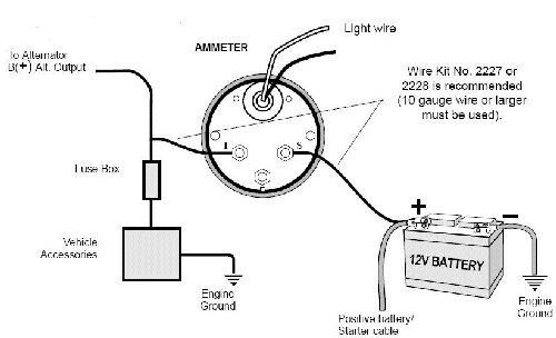
Wire, connect the (s) sender terminal of the 18 gage, wire from fuel tank to gauge. Light wires 10 gauge wire or larger must be used.
Connect one end to terminal post on fuel level sender and the opposite end to the sender (s) terminal spade on back of gauge. The oe ammeter measured the millvolt drop of the wire from one point to the other. Please read these instructions carefully before installing.
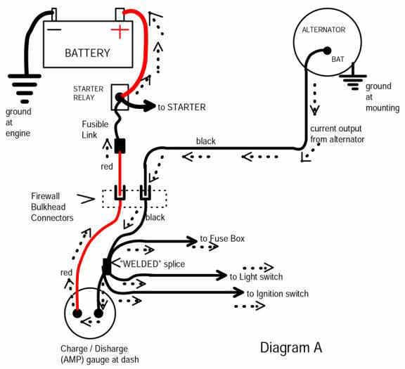
See the diagram at the bottom of this web page: The red wire (a) coming from the discharge side of the ammeter goes through the wiring harness and hooks up to the hot side of the starter solenoid. Example wiring of a typical ammeter installation.
Components of ampere gauge wiring diagram and a few tips. For specific wiring details and safety considerations. Read these instructions thoroughly before making installation.
Ammeter (2¹⁄₁₆ [52 mm] diameter) 1 2. It reveals the elements of the circuit as simplified forms and the power and signal connections between the devices. Do not deviate from assembly or.
Ebay volt amp meter how to in this video we look at how you have to connect of the cheap ebay 100v 10a panel meters if you want to power it and read the valu. The yellow wire (b) coming from the charge side of the ammeter goes through the wiring harness and ties into the 10 awg cable which goes between the hot side of the starter solenoid and the alternator. Also attached is a photo of the instruction sheet from the gm wiring block.
67 wiring harnesses have fusible link protection at the starter and the horn relay. Just two wires for the gauge, oe design. It contains directions and diagrams for various varieties of wiring strategies along with other things like lights, windows, etc.
Do not disable or remove any fusible links in the course of installing an ammeter. The gauge is really not an ammeter. 6) connect a minimum 10awg wire from the “+12v” terminal of the starter solenoid to terminal “i” on the back of the gauge.
Using the wiring kit, attach the wires to the gauge and those previously identified as shown in the instruction sheet that came with your gauge. 1967 corvette ammeter wiring diagram. Variety, either remove the fuse or disconnect one wire connection from the circuit breaker.
Truly we have been noticed that stewart warner gauges wiring diagrams is being one of the most popular subject right now. There are just two things that will be found in any ampere gauge wiring diagram. The #4 red tracer wire from the horn relay is connected to the (+) side of the ammeter per gm's wiring diagram & ynz's.
With your positive battery terminal now connected to the ammeter, you are ready to connect the next wire. Connect ground wire from ground post on gauge to suitable chassis ground. Have mounted the gauge, connect the sender wire to the left connection post.
All instructions refer to viewing from the rear. From model ts to wiring diagrams. The heavy wire from the starter solenoid (battery terminal) to the ammeter goes to the b terminal on the ammeter.
Be sure that all wire connections are tight and that no bare wires are exposed. From there all electrical loads should come out the other side of the terminal block. Reconnect the battery ground cable.
Connect an 8 awg (10.0 mm. June 14, 2021 on 12 volt amp meter wiring diagram. When you connect to the amp gauge you ll use 1 red wire and 1 black wire that will both carry a current.
For most starter solenoid circuits (gm/amc), see wiring diagram c. #158 or equivalent) 1 4. 5) connect a minimum 10awg wire from the alternator “output” to terminal “s” of the amp gauge.
The wire from the other side of the ammeter (l terminal) should go to the terminal block. A circuit is generally composed by various components. Do not over tighten nuts on back.
Another thing which you will find a circuit diagram would be traces. Remove all wires except wire going to battery. Because this was an accessory, the dealer installed it and probably did not show up on the general wiring diagram.
Ammeter wiring diagram wiring diagram is a simplified good enough pictorial representation of an electrical circuit. Once you have connected it to the ammeter, you will then connect it to the alternator terminal post. Vdo mounting bracket and nuts (2) 1 5.
If a new hole is drilled in the firewall a grommet is recommended. Have mounted the gauge, connect the sender wire to the left connection post as shown in diagram 2. Connect an end of the remaining wire from
7) connect a good ground to terminal “g” on the back of the gauge (the ground is only used for the gauge light). Sunpro amp gauge wiring diagram. Installation instructions 1 ˘ˇ ˆ ˙ ˝ ˛ ˘˚˚ ˜˙ ˝!
8) connect dash light power to the spade. Attach the wire as shown in diagram 7, page 7.
Digital Volt Amp Meter Wiring Diagram Gallery

I want to wire in an ammeter to a 12v landrover

Amp Gauge Wiring Diagram Gm Amp Gauge Wiring Diagram Wiring Diagram And Slim Drop A Slim Drop

100 amp, or 60 amp Ammeter? Ford Truck Enthusiasts Forums
Ammeter wiring question The 1947 Present Chevrolet & GMC Truck Message Board Network
Electrical Ammeter Hook up
12 Volt Wire Gauge Chart Best Ac Ammeter Wiring Diagram Free Download Wiring Diagram Xwiaw 12 Rh

Ac Amp Meter Wiring Diagram Collection

Ammeter wiring CJ2A The CJ2A Page Forums
12 Gauge Wire, Amps Nice Glowshift Boost Gauge Wiring CollectionBoat Ammeter Wiring Diagram

12 Volt Wire Gauge Chart New 12 Volt Ammeter Wiring Diagram Free Download Wiring Diagrams Wire
How To Wire Ammeter For DC and AC Ampere Measurement Electrical Online 4u

Digital Volt Amp Meter Wiring Diagram Gallery

Ammeter Gauge Wiring

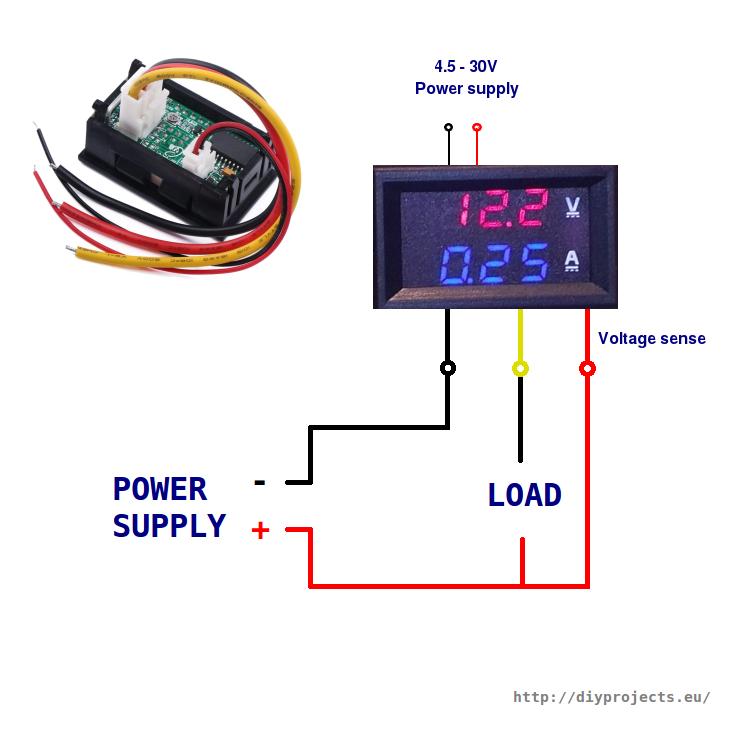
How to wire digital dual display volt and ammeter DIY Projects
Ampere Gauge Wiring Diagram Cadician's Blog
1966 Mustang ammeter wiring Ford Mustang Forum

Car Wiring Diagram Ammeter

Ammeter Wiring The 1947 Present Chevrolet & GMC Truck Message Board Network